

Introduction
The V. Filanovsky field is a key oil asset on the Russian Caspian shelf. Thanks to its unique geology with high reservoir permeability, exceptionally high initial production rates are achieved there. The well‑developed infrastructure of the field also provides a synergistic effect for the implementation of other Caspian projects of LUKOIL [1, 2].
At the offshore ice‑resistant fixed platform (OIRFP) of the V. Filanovsky field, heat recovery boilers UK 11-E-5801 A/B/C/D with a rated capacity of 12 MW were installed. They are designed to heat the primary circuit heat transfer fluid – a 60% aqueous solution of triethylene glycol (TEG) – by using exhaust gases generated during fuel combustion in four Siemens SGT-400 gas turbine units (GTU). The platform equipment was supplied by the Siemens concern, and the heat recovery boilers were provided under contract by the German company BBS GmbH, type ANK 12.000 [3].
Four UK E‑5801A /B/C/D boilers (one standby unit) with a thermal capacity of 12 MW each are installed on the platform. The registers are used to heat the heat transfer fluid up to 150 °C. The heat transfer fluid enters the registers in parallel flows. The design of the scheme does not allow for flow regulation across the registers. The circulation of the heat transfer fluid is ensured by pumps P-5802A/B/C (one standby unit). The pumps force the heat transfer fluid into the heat recovery boiler (HRB), from where it is distributed to the consumers of the central heating point (CHP); secondary circuit heat exchangers of the air conditioning and ventilation system (E-5802A/B); heating of tanks (seawater, oil residues, oily water, process fresh water, TEG, separated fuel, intermediate fuel tank); the heat exchanger of the diesel fuel intake, pumping, and separation system E‑6201; consumers of the residential module‑1; heat exchangers of the fuel gas treatment unit; and the needs of the gas turbine unit.
Problem Statement
The operation of heat recovery boilers UK 11-E-5801 A/B/C/D at the OIRFP of the V. Filanovsky field revealed systemic problems: clogging of the flow passages of the heating surfaces with organic deposits, coke formation from triethylene glycol, and risks associated with the design features of the equipment.
The design inconsistencies and thermal balances embedded in the project did not allow the problems to be compensated for by changing the operating modes. The design solutions for the gas duct and heating surfaces created an increased risk of TEG overheating, which provoked the formation of degradation and oxidation products of the glycol [4].
Residual TEG in the heat recovery boiler’s pipelines contributed to corrosion processes and deposit formation, which negatively affected its efficiency. The presence of air in the pipes created risks of metal overheating during operation and posed a hazard during hydrostatic testing. Considering the need to ensure reliable power supply and the limited space on the upper deck of the OIRFP, a decision was made to reconstruct the heat recovery boiler.
The aim of the study is to identify design flaws in the boilers and develop technical solutions to eliminate them while maintaining the design capacity and making minimal changes to the platform’s supporting structures.
The objectives of the study are as follows: to conduct a comprehensive analysis of the design and operational shortcomings of the UK 11-E-5801 A/B/C/D heat recovery boilers at the OIRFP of the V. Filanovsky field and justify the need for their reconstruction; to confirm the irremediable nature of the identified defects using thermal and gas-dynamic calculations; to develop and propose technical measures related to the modernization of the equipment while maintaining the design capacity and making minimal changes to the supporting structures; to assess the impact of the new registers on the operational characteristics of the boilers – in terms of uniformity of heat absorption, reduction of pressure losses, ensuring complete drainage and air removal, prevention of coke formation – and to confirm the improvement in the reliability and efficiency of the heat recovery boilers after reconstruction.
Research Methods and Results
The analysis of the operational data of the heat recovery boilers was carried out based on the actual operating modes of the UK 11-E-5801 A/B/C/D boilers on the platform. Parameter deviations were recorded, and typical failures and damage patterns were identified (clogging of flow passages, deposits, signs of TEG overheating).
Thermal and gas-dynamic calculations were carried out using the ZuluThermo software package: modeling of the thermal circuit operation under actual operating conditions was performed to assess the distribution of temperatures, gas flow velocities, heat fluxes on the heating surfaces, and to identify risk zones (overheating, non-uniform heat absorption, excessive pressure losses) [5, 6].
As a result of the thermal and gas‑dynamic calculations performed in the ZuluThermo software package (Fig. 1) for the actual operating modes of the thermal circuit of the installed boiler registers, insurmountable inconsistencies were identified.
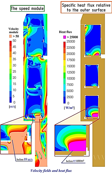
Fig. 1. Results of thermal and gas-dynamic calculations based on actual operating modes of the thermal circuit
(in the ZuluThermo software package): velocity module; specific heat flux relative to the outer surface; velocity fields and heat flux
They led to TEG overheating followed by clogging and blockage of the inner surface of the registers with decomposition products of TEG, as well as the inability to completely drain TEG during drainage and to release air when filling the heat recovery boiler.
The engineering design of the modernization involved the development of technical measures to replace the registers, front removable panels, piping, and internal elements of the flue gas ducts while maintaining the design capacity (12 MW) and minimizing changes to the frame, supporting structures of the casing, and the weight and size characteristics of the equipment. Limitations regarding weight, dimensions, and load‑bearing capacity of the OIRFP structures were also taken into account.
A comparative analysis of design solutions was carried out, which allowed the original flow pattern of the heat transfer fluid and gases in the BBS GmbH boilers to be compared with the proposed scheme based on KUV-12-150 (PK-142) registers manufactured by Podolsk Machine-Building Plant JSC [7] (in terms of flow organization, drainage and air removal capabilities, and coil arrangement).
The use of new custom-made KUV-12-150 (PK-142) registers made it possible to implement a series-parallel flow scheme for the heat transfer fluid. This solution ensured complete drainage of the system and efficient air removal during filling, which significantly improved the operational characteristics of the heat recovery boiler (Fig. 2).
No changes to the gas flow pattern in the heat recovery boiler were envisaged. The numbers indicate the start and end of the sections for the hydraulic calculation.

Fig. 2. Schematic diagram of the application of the new registers
This also made it possible to eliminate pressure losses caused by turns of the gas jets, reduce the non-uniformity of the velocity field in front of the registers and the non-uniformity of heat absorption by the coils in the registers, and ensure a sufficiently uniform velocity field profile at the inlet to Register 1 for reliable operation of its coils and avoid creating excessive gas pressure losses.
It also ensured that the straight-through smooth-tube Register 1 had a low TEG temperature in the first, most heated rows of tubes, moderate heat absorption by the coils, alignment of the velocity field before Register 2, and that Registers 2 and 3 operated with gases having fairly uniform velocity fields, heating the TEG as efficiently as possible with minimal differences in TEG temperatures between the coils (Fig. 3).

Fig. 3. Flow diagram of gases in the heat exchanger
Conclusion
The irremediable nature of the identified defects (TEG overheating, coke formation, incomplete drainage, risks of corrosion and emergency situations) by adjusting the operating modes was confirmed – calculations in ZuluThermo showed the fundamental limitations of the original design.
In the development and practical implementation of the adapted modernization scheme under the strict spatial and weight constraints of the offshore platform,
a series-parallel flow scheme for the heat transfer fluid in the new KUV-12-150 (PK-142) registers was proposed and implemented. It simultaneously ensures reduced hydraulic losses, alignment of velocity and heat flux fields, and complete drainage and air removal – without increasing the dimensions or making significant changes to the supporting structures [8].
The design solution involving the vertical arrangement of the coils with a downward TEG flow was applied for the first time in this size range of heat recovery boilers to prevent coke formation in the most thermally stressed zones (in particular, in Register 3) by maintaining moderate temperatures in the initial sections of the tubes and eliminating stagnant phenomena. In the new design by Podolsk Machine-Building Plant JSC, gases from the bypass heat one tube in each of the 16 coils, effectively preventing the formation of coke deposits.
A reduction in the non-uniformity of the velocity field in front of the registers and alignment of heat absorption by the coils was achieved; pressure losses due to turns of the gas jets were reduced. A decrease in flow rate in the HRB will not trigger a chain reaction of coke formation because the coils are operating under fairly similar conditions. The low TEG temperature in the tubes (temperature before the HRB- +5 °C) increases their resistance to TEG overheating.
Complete drainage of the circuit and efficient air removal when filling the boiler were ensured, which eliminated the accumulation of residual TEG and the associated corrosion processes.
Overall, the new register design provides a comprehensive improvement in the operational characteristics of the heat recovery boilers, expressed in an integrated approach to improving equipment reliability. This approach combines computational justification (thermal and gas-dynamic models), targeted replacement of critical components, and preservation of design characteristics, forming a reproducible methodology for the reconstruction of heat exchange equipment in confined conditions of offshore facilities.